In most cases the fix is to replace electrolytic capacitors C5, C7, C9, C13, C15, and the ceramic C2 (See schematic) to get it back to normal. Once it’s working, use the speed calibration process from the service manual. Also check the voltage on the zener diode (between C2 and C15 on the board) to be about 9V.
If replacing the capacitors listed above does not resolve the issue, that probably means that one of the traces had corroded and disconnected. Check voltage on the ground and power pins on IC1 and IC2 with a voltmeter, and continuity of all traces on the board with an ohmmeter, in particular on the left side of the board. You can also compare signals at the ends of traces with an oscilloscope while it’s running. I’ve seen two cases where the trace between C7 and R4 has corroded right at the edge of the pad of C7, one case with the trace between IC1 and C16, on the edge of IC1 pad, and one case with the ground bus between C7 and the zener diode.
Parts that I use in repair:
https://www.mouser.com/ProductDetail/667-EEE-1CA100SR - C5, C13, C15
https://www.mouser.com/ProductDetail/667-EEE-1VA4R7SR - C7
https://www.mouser.com/ProductDetail/667-EEE-1HA010SR - C9
https://www.mouser.com/ProductDetail/581-12065C473KAZ2A - C2
https://www.mouser.com/ProductDetail/78-TZMB9V1 - Z1
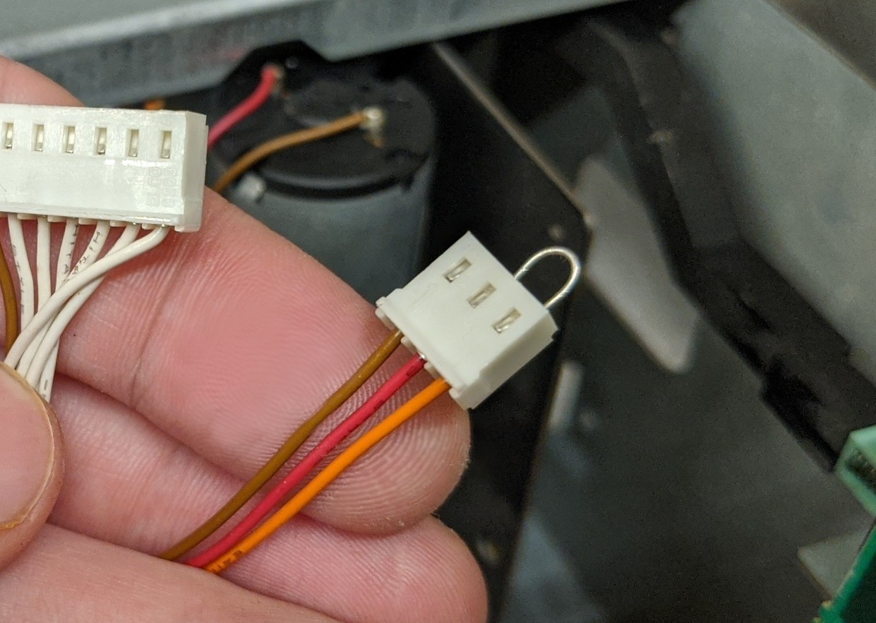
To pull out the transport for service you will need to disconnect two cables running to the speed control board on the front left side of the machine. The capstan will not run without the three- or four-pin connector plugged in, but there is a way to simulate the connection without having to pull out the speed control board if you need to test the repair or perform other service that requires the capstan to be running. Use a piece of wire to connect red and orange wires on the connector (same on a four-wire connector, orange and red will be the middle two wires):