Capstan Motor
Cause of most capstan motor faults #
Most issues are caused by faulty electrolytic capacitors on the capstan motor board, which I believe were early generation of the technology. Replacing the capacitors with far more durable and reliable modern equivalents usually resolves the issue. If it does not, and the motor is still noisy, uneven or not running at all, then there are likely corroded traces, and in some cases faulty IC1 or IC3.
Running capstan motor without connecting it to the pitch control board #
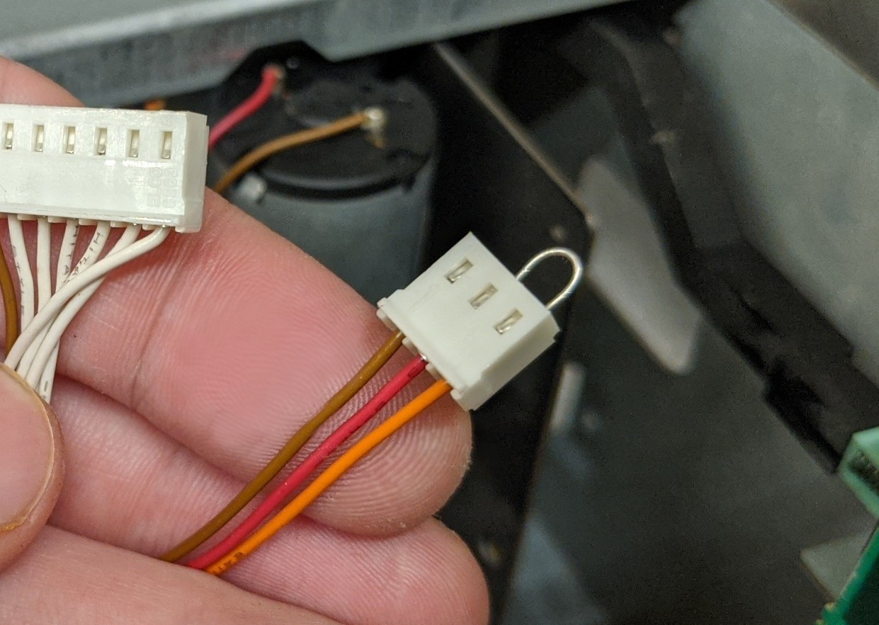
To pull out the transport for service you will need to disconnect two cables running to the speed control board on the front left side of the machine. The capstan will not run without the three- or four-pin connector plugged in, but there is a way to simulate the connection without having to pull out the speed control board if you need to test the repair or perform other service that requires the capstan to be running. Use a wire jumper connect red and orange wires on the connector (same on a four-wire connector, orange and red will be the middle two wires):

Capstan not running at all #
Make sure the “9.6” solder brigde is shorted and “4.8” solder bridge is open.
Most likely cause is corroded or cracked/damaged trace(s) on the capstan board.
If the motor runs with a wire jumper as described above, but not when connected to the pitch control board (rare), the fault is on the pitch control board or the wire loom.
Noisy capstan that runs too fast #
In most cases the fix is to replace electrolytic capacitors C5, C7, C9, C13, C15, and the ceramic C2 (See schematic) to get it back to normal. Once it’s working, use the speed calibration process from the service manual. Also check the voltage on the zener diode (between C2 and C15 on the board) to be about 9V.
If replacing the capacitors listed above does not resolve the issue, that probably means that one of the traces had corroded and disconnected. Check voltage on the ground and power pins on IC1 and IC2 with a voltmeter, and continuity of all traces on the board with an ohmmeter, in particular on the left side of the board. You can also compare signals at the ends of traces with an oscilloscope while it’s running. I’ve seen two cases where the trace between C7 and R4 has corroded right at the edge of the pad of C7, one case with the trace between IC1 and C16, on the edge of IC1 pad, and one case with the ground bus between C7 and the zener diode.
Parts that I use in repair:
https://www.mouser.com/ProductDetail/667-EEE-1CA100SR - C5, C13, C15 (10uF)
https://www.mouser.com/ProductDetail/667-EEE-1VA4R7SR - C7 (4.7uF)
https://www.mouser.com/ProductDetail/667-EEE-1HA010SR - C9 (1uF)
https://www.mouser.com/ProductDetail/581-12065C473KAZ2A - C2 (47nF)
https://www.mouser.com/ProductDetail/78-TZMB9V1 - Z1 (9.1V)
Factory value of C2 is apparently 1nF, which I find insufficient for a ripple-free control voltage supplied to IC3.
Excessive wow and flutter #
Manifests itself as distortion or “warbling”:
Most likely cause, if it’s not mechanical, is either bad C16 or trace corrosion around C16 and R3.